


- 增强的性能
- 广泛的应用
- 易于安装和配置
- 非接触式夹紧式超声波换能器
- 适用于各种管材和尺寸
- 大型背光流量显示和累加器
- 隔离4-20mA输出
- 2个可编程控制继电器
- 可选MODBUS??RTU或HART输出
- 应用优化可用
- 128MB数据记录器
TTFM 6.1 Transit Time Flow Meter
- Enhanced Performance
- Wide Range of Applications
- Easy to Install and Configure
- Non-Contacting Clamp-on Ultrasonic Transducers
- Works on a Large Variety of Pipe Materials and Sizes
- Large Backlit Flow Rate Display and Totalizer
- Isolated 4-20mA Output
- 2 Programmable Control Relays
- Optional MODBUS??RTU or HART Output
- Application Optimization Available
- 128MB Data Logger
准确测量相对清洁的非充气液体的流速,如饮用水,原水,冷却水,去离子水或反渗透水,全油管中的油和化学品。超声波换能器安装在管道外部而不会关闭流量。流量显示在大型背光显示屏上,以及总体积,信号强度,继电器状态和其他诊断值。使用内置控制继电器作为流量报警或音量累加。将隔离的4-20mA输出连接到PLC或控制器。128MB数据记录器是标准配置,能够捕获多达2600万个数据点。可通过RS-485选配MODBUS RTU,可连接自动化系统。
TTFM 6.1适用于各种管道尺寸和材料,包括碳钢,不锈钢,球墨铸铁,混凝土衬里球墨铸铁,铸铁,PVC,PVDF,玻璃纤维,铜,黄铜,铝和带有环氧树脂粘合衬里的管道,橡胶和铁氟龙。
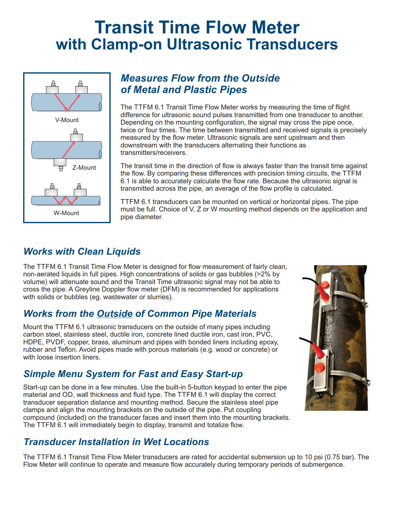
TTFM 6.1 Transit Time Flow Meter通过测量从一个传感器传输到另一个传感器的超声波脉冲的“传输时间”或“飞行时间”来运行。根据安装配置,信号可能会穿过管道一次,两次或四次。为了测量流量,在上游和下游行进的超声信号之间比较传播时间。
TTFM 6.1标准功能包括:
- 一对SE16B超声波换能器 – 用于2“至48”(50 mm至1200 mm)管道的夹紧
- 传感器电缆 – 对25英尺/ 7.6米三轴带BNC连接器
- 流量范围:±0.07至40英尺/秒(±0.02至12米/秒)
- 安装 – 不锈钢传感器安装支架和夹具,校准棒和硅胶耦合复合套件
- 外壳 – 防水,NEMA4X(IP66)聚酯和聚碳酸酯
- 显示屏 – 白色背光矩阵
- 累加器 – 14位数
- 编程 – 内置5键键盘
- 输出 – 隔离4-20mA(1000欧姆)
- 2控制继电器 – 5安培,SPDT – 可编程用于流量比例脉冲输出和/或流量报警
- 电源输入 – 100-240VAC 50 / 60Hz,最大10VA(可选:9-36VDC,最大10瓦)
- Data Logger – 128MB存储容量,2600万个数据点,格式化为.csv或.lg2,用于Greyline Logger软件
- 电涌保护和RFI滤波器 – 交流,传感器,4-20mA
- 即插即用选项包括MODBUS RTU输出和额外的控制继电器
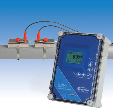
Accurately measure the flow rate of relatively clean, non-aerated liquids like potable water, raw water, cooling water, de-ionized or reverse-osmosis water, oils and chemicals in full pipes. Ultrasonic transducers mount on the outside of a pipe without shutting down flow. Flow rate is displayed on the large, backlit display, along with total volume, signal strength, relay status, and other diagnostic values. Use the built-in control relays as flow alarms or volume totalization. Connect the isolated 4-20mA output to PLC’s or controllers. A 128MB data logger is standard, capable of capturing up to 26 million data points. Optional MODBUS RTU via RS-485 available for connection to automation systems.
The TTFM 6.1 works on a wide range of pipe sizes and materials including carbon steel, stainless steel, ductile iron, concrete lined ductile iron, cast iron, PVC, PVDF, fiberglass, copper, brass, aluminum and pipes with bonded liners including epoxy, rubber and Teflon.
The TTFM 6.1 Transit Time Flow Meter operates by measuring the “transit time” or “time of flight” for ultrasonic sound pulses transmitted from one transducer to another. Depending on the mounting configuration, the signal may cross the pipe once, twice or four times. To measure flow the transit time is compared between ultrasonic signals travelling upstream and downstream.
TTFM 6.1 Standard Features Include:
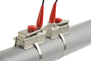
- One pair of SE16B ultrasonic transducers – clamp-on for 2” to 48” (50 mm to 1200 mm) pipes
- Sensor cables – pair 25 ft / 7.6 m triaxial with BNC connectors
- Flow rate range: ± 0.07 to 40 ft/sec (± 0.02 to 12 m/sec)
- Installation – stainless steel transducer mounting brackets and clamps, alignment bar and silicone coupling compound kit
- Enclosure – watertight, NEMA4X (IP66) polyester and polycarbonate
- Display – white, backlit matrix
- Totalizer – 14 digits
- Programming – built-in 5-button keypad
- Output – isolated 4-20mA (1000 ohm)
- 2 Control relays – 5 amp, SPDT – programmable for flow proportional pulse output, and/or flow alarm
- Power input – 100-240VAC 50/60Hz, 10VA maximum (Optional: 9-36VDC, 10 Watts maximum)
- Data Logger – 128MB storage capacity, 26 million data points, formattable as .csv or .lg2 for Greyline Logger Software
- Electrical surge protection and RFI filters – AC, sensor, 4-20mA
- Plug-and-play options including MODBUS RTU output and extra control relays
本规范涉及一种夹式超声波传输时间
流量计由Greyline Instruments,Largo,Florida/Long Sault,Ontario制造。仪表应提供非侵入式流量测量、方向
全管流量的显示、总量计算和传输。
A.性能规范
超声波流量计的精度应为读数的±1%或±0.015 ft/sec(±0.0046 m/sec),以较大者为准。
重复性和线性度为±0.25%。
应在流速为±0.07至40 ft/sec(±0.02至12 m/sec)且固体或气泡小于2%的完整管道中相对清洁的液体上操作。
操作任何金属或塑料、声波传导材料,包括碳钢、不锈钢、球墨铸铁、混凝土内衬球墨铸铁、铸铁、聚氯乙烯、聚偏氟乙烯、玻璃纤维、镀锌钢、铜、黄铜以及带有环氧树脂、橡胶和特氟龙等粘合衬层的管道。
当订购时提供管道材料、管道尺寸、壁厚、流体类型、流体温度和最大流速等信息时,应针对应用对超声波流量计进行优化和预编程。
B.传感器(流量传感器)
流量计应具有双发送/接收夹式传感器。
传感器应在-40°F至300°F(-40°C至150°C)的温度下连续工作。
标准传感器对应设计为安装在内径为2“至48”(50 mm至1200 mm)的管道上。
有25英尺(7.6米)长的三轴电缆,从带有BNC连接器的电子设备到传感器。
应包括制造商推荐的传感器耦合化合物。应包括带管夹的不锈钢安装硬件。
应包括用于传感器在高达10 psi(0.75 bar)的潮湿或水下条件下运行的BNC密封套。
传感器的等级应为I级2类A、B、C和D组位置的非易燃性。
C.电子
电子设备应安装在防水、防尘的NEMA4X(IP 66)聚酯和聚碳酸酯外壳内,带密封防碎窗口,并适用于墙壁安装。
流量计电子设备应设计为在-5°F至140°F(-20°C至60°C)的温度下工作。发射机电路和校准频率标准应为晶体控制。变送器应采用100-240VAC 50/60Hz电源,要求小于10VA。
变送器应包括一个内置的5键校准系统,操作员可通过菜单校准系统的视觉提示选择参数。不接受需要通过参数代码或外部校准器进行校准的系统。
4-20mA应与流量成比例并隔离,具有可编程零点和满刻度偏移。最大电阻负载应为1000欧姆。它应包括附近雷击时自动高压泄放。
电子设备应包括噪声抑制电路,以过滤电气干扰。
电子设备应具有白色背光矩阵LCD显示屏,以用户选择的工程单位显示流量、校准单位、继电器状态、信号强度、测量的声速和14位积算器。
电子设备应具有2个额定5安培SPDT的控制继电器。继电器应可编程用于流量比例脉冲输出,或作为具有单独开/关设定点的流量警报。
电子设备应显示并汇总正向和反向流量。
电子设备应具有内置数据记录器,能够存储高达128MB的数据。数据可以通过仪表前面板上的USB A型端口下载到闪存驱动器。
电子设备应为模块化,并可通过插入式电路板进行现场更换。仪器应自动检测和加载软件菜单,以供现场安装选项使用。
E.根据需要插入规范的可选功能:
传感器电缆应为50 ft(15 m)长的三轴电缆,带有BNC传感器连接。
传感器电缆应为加长屏蔽三轴对,最大500 ft(150m),带有NEMA4X(IP 66)接线盒。
电子设备应包括通过RS-485或HART的Modbus RTU输出。Modbus的数据点应包括流量、流量总计、前一天的平均流量、前一天的体积总计、累加器复位、继电器输出状态、信号强度、测量的声速、运行时间、传感器连接状态、记录器状态和使用的百分比日志。HART应为7.0版,具有与艾默生475 HART字段兼容的DD文件。
传感器的本质安全等级应为I级,1类,C和D组;II级,E、F和G组;III级;4类危险场所。
电子设备应具有恒温控制的交流电源外壳加热器,用于温度低于-5°F(-20°C)的位置的冷凝保护。
电子设备的电源输入应为9-32Vdc,要求小于10瓦。
电子设备应具有4个附加(共6个)控制继电器,额定5安培SPDT,可编程用于流量警报或流量积算器脉冲。
E.制造商
该仪器应为TTFM 6.1型夹持式时间流量计,由Greyline仪器制造,并保证一年内不会出现材料和工艺缺陷。
规格如有更改,恕不另行通知。如果您在申请中需要更多信息或建议,请联系Greyline。我们可以提供报价,并向贵公司所在地区的Greyline销售代表咨询。
This specification covers a Clamp-On Transit-Time Ultrasonic Flow Meter as manufactured by Greyline Instruments, Largo, Florida / Long Sault, Ontario. The meter shall provide for non-intrusive flow measurement, direction indication, volume totalizing, and transmitting of the flow rate in a full pipe.
A. PERFORMANCE SPECIFICATIONS
The ultrasonic flow meter shall have an accuracy of ±1% of reading or ±0.015 ft/sec (±0.0046 m/sec), whichever is greater. Have repeatability and linearity of ±0.25%.
Shall operate on relatively clean liquids in full pipes with less than 2% solids or gas bubbles at flow velocities from ±0.07 to 40 ft/sec (±0.02 to 12m/sec).
Operate on any metal, or plastic, sonic conducting material including carbon steel, stainless steel, ductile iron, concrete lined ductile iron, cast iron, PVC, PVDF, fiberglass, galvanized steel, copper, brass and pipes with bonded liners including epoxy, rubber and Teflon.
The ultrasonic flow meter shall be optimized and pre-programmed for the application when information like pipe material, pipe size, wall thickness, fluid type, fluid temperature, and max flow rate are provided at time of order.
B. TRANSDUCERS (FLOW SENSORS)
The flow meter shall have a dual transmitting/receiving, clamp-on transducers.
The transducers shall operate continuously at temperatures from -40°F to 300°F (-40°C to 150°C).
The standard transducer pair shall be designed to install on pipes with inside diameter ranging from 2″ to 48″ (50 mm to 1200 mm).
Have 25 ft (7.6 m) length triaxial cables from the electronics with BNC connectors to transducers.
Shall include manufacturer’s recommended sensor coupling compound. Shall include stainless steel mounting hardware with pipe clamps.
Shall include BNC seal jackets for transducer operation in wet or submerged conditions up to 10 psi (0.75 bar).
Transducers shall be rated non-incendive for Class I, Division 2, Groups A, B, C & D locations.
C. ELECTRONICS
The electronics shall be housed in a watertight and dust tight NEMA4X (IP 66) polyester and polycarbonate enclosure with a gasketed shatter proof window, and suitable for wall mounting.
Flow meter electronics shall be designed to operate at temperatures from -5°F to 140°F (-20°C to 60°C). The transmitter circuit and calibration frequency standard shall be crystal controlled. The transmitter shall be powered by 100-240VAC 50/60Hz requiring less than 10VA.
The transmitter shall include a built-in 5-Key calibration system with operator selection of parameters through visual prompts from a Menu calibration system. Systems requiring calibration by Parameter codes or external calibrators shall not be accepted.
The 4-20mA shall be flow proportional and isolated, with programmable zero and full-scale offsets. Maximum resistive load shall be 1000 ohms. It shall include automatic high voltage bleeds for nearby lightning strikes.
Electronics shall include noise suppression circuitry to filter electrical interference.
Electronics shall have a white, backlit matrix LCD display indicating flow rate in user-selected engineering units, units of calibration, relay states, signal strength, measured fluid speed of sound, and 14-digit totalizer.
Electronics shall have 2 control relays rated 5 amps SPDT. Relays shall be programmable for flow proportional pulse output, or as flow rate alarms with separate ON/OFF set points.
Electronics shall display and totalize forward and reverse flow.
Electronics shall have built-in data logger capable of storing up to 128MB of data. Data can be downloaded to flash drive via USB type-A port on the meter’s front panel.
Electronics shall be modular and field replaceable by means of plug-in circuit boards. The instrument shall detect and load software menus automatically for field-installed options.
D. OPTIONAL FEATURES FOR INSERTION IN SPECIFICATION AS REQUIRED:
Transducer cables shall be 50 ft (15m) length triaxial with BNC transducer connections.
Transducer cable shall be extended length shielded triaxial pair up to 500 ft (150m) with NEMA4X (IP 66) Junction Box.
Electronics shall include a MODBUS RTU output via RS-485 or HART. Data points for Modbus shall include flow rate, flow total, previous day’s average flow rate, previous day’s volume total, totalizer reset, relay output status, signal strength, measured fluid speed of sound, run time, transducer connection status, logger status, and percent log used. HART shall be version 7.0, with DD files compatible with Emerson 475 HART Field.
Transducers shall be rated Intrinsically Safe for Class I, Division 1, Groups C and D; Class II, Groups E, F and G; Class III; Type 4 hazardous locations.
Electronics shall have a thermostatically controlled AC-powered enclosure heater for condensation protection in locations with temperature below -5°F (-20°C).
Electronics shall have power input of 9-32VDC requiring less than 10 Watts.
Electronics shall have 4 additional (6 total) control relays, rated 5 amps SPDT and programmable for flow rate alarms or flow totalizer pulse.
E. MANUFACTURER
The instrument shall be a Model TTFM 6.1 Clamp-On Transit-Time Flow Meter as manufactured by Greyline Instruments, and warranted against defects in materials and workmanship for one year.
Specifications are subject to change without notice. Please contact Greyline if you need more information or for advice in your application. We can provide quotations and refer you to the Greyline sales representative in your area.
流量计运作原理
仪器电子设备测量从发送声音到回声返回所需的时间。根据空气中的声速,可以高精度计算出液体表面与传感器的准确距离(0.25%范围)。
由于声速受空气温度的影响,灰线超声波液位传感器包括一个内置的温度传感器。水平/距离测量在传感器的整个工作温度范围内自动进行温度补偿。
传感器的位置应使其能清楚地“看到”液体表面,远离梯子、管道或其他障碍物。Greyline建议每10英尺深度距离侧壁1英尺(每3米深度300毫米)。来自搅拌器的假回波(在传感器下扫过)、湍流和波可以被仪器过滤和忽略。
Greyline模型的范围从简单的4-20mA液位指示发送器,到复杂的监控、控制和数据记录模型。返回greyline产品了解级别模型详细信息和规格。有关包括超声波在内的各种液位仪表技术的信息,请参阅废水液位测量技术。
测量管外脏污或充气液体的流量
多普勒效应由奥地利物理学家克里斯蒂安·多普勒于1842年提出。我们每天都能听到多普勒的例子:火车经过时的汽笛声改变音调,或者赛车驶过我们的位置时的排气噪音。
多普勒技术只适用于含有固体或气泡的液体来反射其信号。这些是“困难”的液体,可能会损坏常规流量计:泥浆、污泥、废水、磨料、粘性和腐蚀性化学品。由于传感器安装在管道外部,因此没有压降,也没有流动障碍物。
为了获得很好性能,多普勒传感器应安装在远离湍流产生装置(如弯管和三通)的地方,远离速度增加装置(如控制阀和泵)。典型精度为满刻度的±2%。多普勒仪器包括一个夹式超声波传感器、连接电缆和一个电子外壳,可以安装在附近方便的位置(500英尺/152米范围内)。传感器可以本质安全地额定安装在危险的额定位置。
需要非常精确的定时电路,但当传感器可以安装在流量均匀分布的管段上时,1%的精度非常典型。
由于超声波信号必须穿过管道到达接收传感器,因此流体中不得含有大量气泡或固体(小于2%)。否则高频声音会减弱,太弱,无法穿过管道。应用包括饮用水、冷却水、水/乙二醇溶液、液压油、燃油和化学品。
渡越时间传感器通常工作在1-2兆赫的频率。高频设计通常用于较小的管道,低频设计用于直径达数米的大型管道。
水槽和堰是专门设计的渠道形状,以表征水流。常见的类型有矩形堰、V型槽堰、Parshall水槽和Palmer Bowlus水槽。水槽或堰型的选择取决于应用:流速、渠道形状和水的固体含量。请联系Greyline Instruments以获取有关为您的应用选择合适水槽或堰的建议。
灰线明渠流量计可以通过菜单选择校准到水槽或堰。明渠流量计电子设备使用内部公式计算流量(流量=k h n,其中“k”和“n”为常数,“h”为仪器测量的压头)。通过直接输入“k”和“n”常数,可以对不常见或自定义水槽进行校准。Greyline还提供了一个PC软件程序“find k&n”,用于根据水槽或堰流图开发校准常数。
Greyline明渠流量计包括非接触式超声波传感器、连接电缆和电子外壳,可安装在附近方便的位置(500 ft/152 m内)。传感器可以本质安全地额定安装在危险的额定位置。仪器显示、汇总、传输和控制,有些型号包括数据记录/流量报告系统。
在没有水槽或堰的情况下测量明渠流量。面积速度流量计连续测量水位和流速,以计算明渠或管道中的流量。
超声波传感器安装在管道或通道的底部。为了测量水位,传感器发送超声波脉冲,这些脉冲通过水传播并从液体表面反射出来。仪器精确测量回声返回传感器所需的时间。根据水中声速,测量声级精度为±0.25%。
用连续注入水中的超声多普勒信号测量流速。这种高频声音(640kHz)从悬浮在液体中的颗粒或气泡反射回传感器。如果流体在运动,回声以与流速成比例的变化频率返回。利用该技术,仪器测量流速的精度为±2%。
greyline面积流速流量计工作在部分满管和溢流管、矩形、梯形和蛋形通道中。
可选-单独的液位和速度传感器
一个单独的向下看超声波传感器可用于高充气或湍流应用。它通过将超声波脉冲通过空气传输到液体表面来测量液位,精度为±0.25%。在水位传感器的基础上,采用水下多普勒速度传感器对水位进行测量。
HOW IT WORKS
The instrument electronics measure the time it takes from transmitted sound to return of the echo. With reference to the speed of sound in air, the exact distance of the liquid surface from the sensor can be calculated with high accuracy (±0.25% of maximum range).
Since the speed of sound is affected by air temperature, Greyline ultrasonic level sensors include a built-in temperature sensor. Level/distance measurements are automatically temperature compensated throughout the operating temperature range of the sensor.
The sensor should be positioned so that it has a clear “view” of the liquid surface and away from ladders, pipes or other obstructions. Greyline recommends 1 ft. from the sidewall for every 10 ft. depth (300 mm for every 3 m depth). False echoes from agitators (sweeping under the sensor), turbulence and waves can be filtered and disregarded by the instrument.
Greyline models range from simple 4-20mA level indicating transmitters, to sophisticated monitoring, controlling and data logging models. Return to Greyline Products for Level model details and specifications. For information on a wide range of level instrument technologies including ultrasonics, read Wastewater Level Measurement Techniques.
Doppler flow meters measure flow from outside a pipe with a clamp-on sensor. Greyline Doppler meters continuously transmit high frequency sound (640 kHz) that travels through the pipe wall and into the flowing liquid. Sound is reflected back to the sensor from solids or bubbles in the fluid. If the fluid is in motion, the echoes return at an altered frequency proportionate to flow velocity. Doppler flow meters continuously measure this frequency shift to calculate flow.
Measure Flow of dirty or aerated Liquids from Outside a Pipe
The Doppler effect was first documented in 1842 by Christian Doppler, an Austrian physicist. We hear everyday examples of Doppler: the sound of a train whistle changing pitch as it passes by, or the exhaust noise from a race car as it speeds past our location.
The Doppler technique only works on liquids which contain solids or gas bubbles to reflect its signal. These are “difficult” liquids that may damage regular flow meters: slurries, sludge, wastewater, abrasives, viscous and corrosive chemicals. Because the sensor mounts on the outside of the pipe, there is no pressure drop and no obstruction to flow.
For best performance Doppler sensors should be mounted away from turbulence creating devices like pipe elbows and tees, and away from velocity increasing devices like controlling valves and pumps. Typical accuracy is ±2% of full scale. Doppler instruments include a clamp-on ultrasonic sensor, connecting cable and an electronics enclosure which can be mounted at a convenient location nearby (within 500 ft / 152 m). Sensors can be rated intrinsically safe for mounting in hazardous-rated locations.
Very accurate timing circuits are required but 1% accuracy is quite typical when the transducers can be mounted on a pipe section with evenly distributed flow.
Because the ultrasonic signal must cross the pipe to a receiving transducer, the fluid must not contain a significant concentration of bubbles or solids (less than 2%). Otherwise the high frequency sound will be attenuated and too weak to traverse the pipe. Applications include potable water, cooling water, water/glycol solutions, hydraulic oil, fuel oils and chemicals.
Transit Time transducers typically operate in the 1-2 MHz frequencies. Higher frequency designs are normally used in smaller pipes and lower frequencies for large pipes up to several meters in diameter.
Flumes and weirs are specially designed channel shapes that characterize the flow of water. Common types are Rectangular Weirs, V-Notch Weirs, Parshall flumes and Palmer Bowlus flumes. The choice of flume or weir type depends on the application: flow rate, channel shape and solids content of the water. Contact Greyline Instruments for advice on selection of a suitable flume or weir for your application.
Greyline open channel flow meters can be calibrated to any flume or weir by menu selection. The open channel flow meter electronics use an internal formula to calculate flow rate (Flow = K Hn, where ‘K’ and ‘n’ are constants and ‘H’ is Head as measured by the instrument). Calibration to uncommon or custom flumes can be done by direct entry of ‘K’ and ‘n’ constants. Greyline also offers a PC software program “Find K&n” to develop calibration constants from a flume or weir flow chart.
Greyline open channel flow meters include a non-contacting ultrasonic sensor, connecting cable and an electronics enclosure which can be mounted at a convenient location nearby (within 500 ft / 152 m). Sensors can be rated intrinsically safe for mounting in hazardous-rated locations. The instruments display, totalize, transmit and control, and some models include data logging/flow reporting systems.
Measure open channel flow without a flume or weir An Area-Velocity Flow Meter continuously measures both Level and Velocity to calculate flow volume in an open channel or pipe.
The ultrasonic sensor is installed at the bottom of a pipe or channel. To measure water level the sensor transmits ultrasonic pulses that travel through the water and reflect off the liquid surface. The instrument precisely measures the time it takes for echoes to return to the sensor. Based on the speed of sound in water, the level is measured with accuracy of ±0.25%.
Flow velocity is measured with an ultrasonic Doppler signal continuously injected into the water. This high frequency sound (640 KHz) is reflected back to the sensor from particles or bubbles suspended in the liquid. If the fluid is in motion, the echoes return at an altered frequency proportionate to flow velocity. With this technique the instrument measures flow velocity with accuracy of ±2%.
Greyline Area-Velocity Flow Meters work in partially full and surcharged pipes, rectangular, trapezoid and egg-shaped channels.
Optional – Separate Level and Velocity Sensors
A separate down-looking ultrasonic sensor can be used for highly aerated or turbulent flow applications. It measures level by transmitting ultrasonic pulses through the air to the liquid surface with accuracy of ±0.25%. Along with the level sensor, a submerged Doppler velocity sensor is used to measure the water velocity.


