


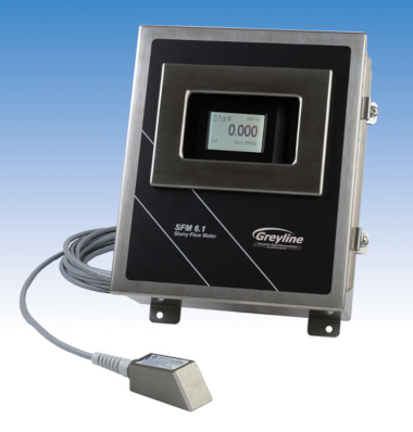
SFM 6.1超声波浆料流量计
- 针对浆料进行了优化
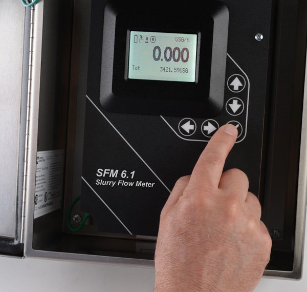
- 简单,直观的设置
- 5按钮菜单系统
- 隔离4-20mA输出
- 最多6个控制继电器
- 可选的内置数据记录器
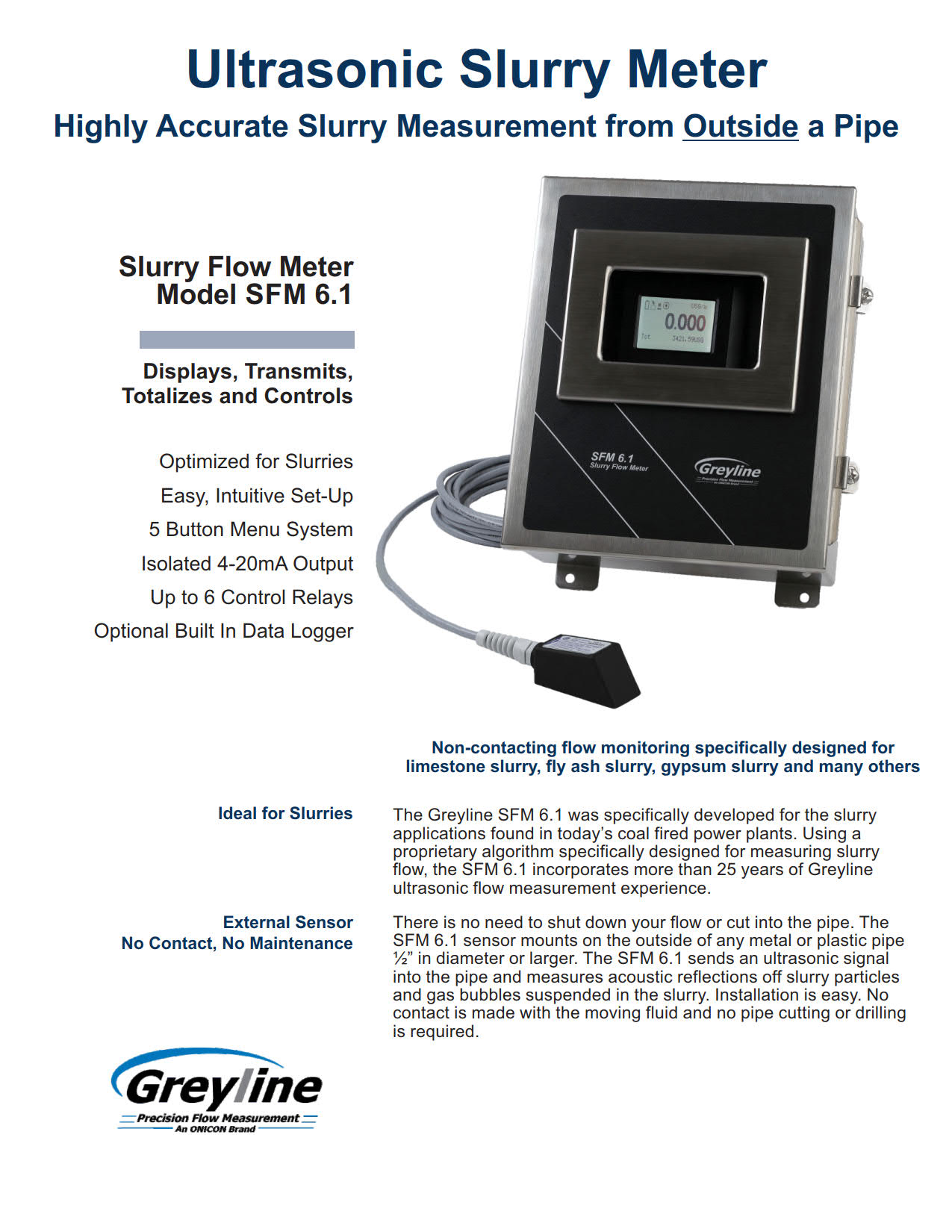
SFM 6.1 Ultrasonic Slurry Flow Meter
- Optimized for Slurries
- Easy, Intuitive Set-Up
- 5 Button Menu System
- Isolated 4-20mA Output
- Up to 6 Control Relays
- Optional Built In Data Logger
非接触式流量监测为石灰石浆料,粉煤灰浆料,石膏浆料和许多其他设计
Greyline SFM 6.1为燃煤发电厂的泥浆应用而开发。SFM 6.1采用用于测量浆料流量的算法,具有Greyline超声波流量测量经验。
SFM 6.1浆料流量计在能够破坏常规接触流量计的应用中效果很好。由于传感器安装在管道外部,因此不会受到磨蚀性浆料或刺激性化学品的影响。没有阻碍流动和压力下降。
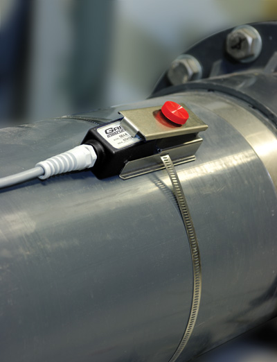
易于安装
每个SFM 6.1浆料流量计都包括一个带式超声波传感器,一个可调节的不锈钢安装夹具和传感器耦合化合物。传感器安装在任何直径为?“(12.7 mm)或更大的管道外侧。安装只需几分钟。无需关闭流量。
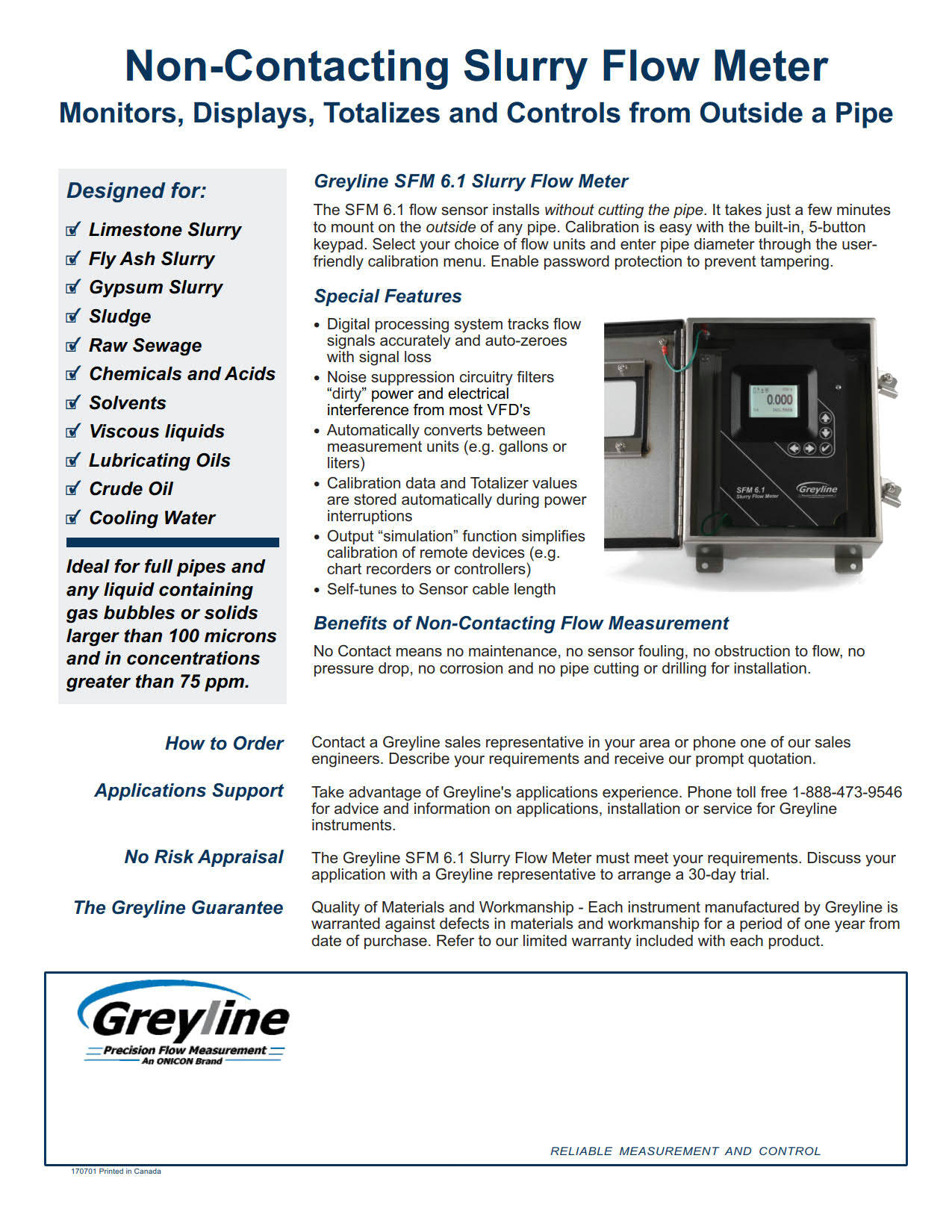
特殊功能
- 数字处理系统准确地跟踪流量信号,并在信号丢失时自动归零
- 噪声抑制电路可过滤大多数VFD的“脏”功率和电气干扰
- 在测量单位之间自动转换(例如加仑或升)
- 电源中断期间会自动存储校准数据和累加器值
- 输出“模拟”功能简化了远程设备(例如图表记录器或控制器)的校准
- 自调谐到传感器电缆长度
Non-contacting flow monitoring specifically designed for limestone slurry, fly ash slurry, gypsum slurry and many others
The Greyline SFM 6.1 was specifically developed for the slurry applications found in today’s coal fired power plants. Using a proprietary algorithm specifically designed for measuring slurry flow, the SFM 6.1 incorporates more than 25 years of Greyline ultrasonic flow measurement experience.
The SFM 6.1 Slurry Flow Meter works best in applications that would defeat regular contacting flow meters. Because the Sensor is mounted on the outside of the pipe, it is unaffected by abrasive slurries or harsh chemicals. There is no obstruction to flow and no pressure drop.
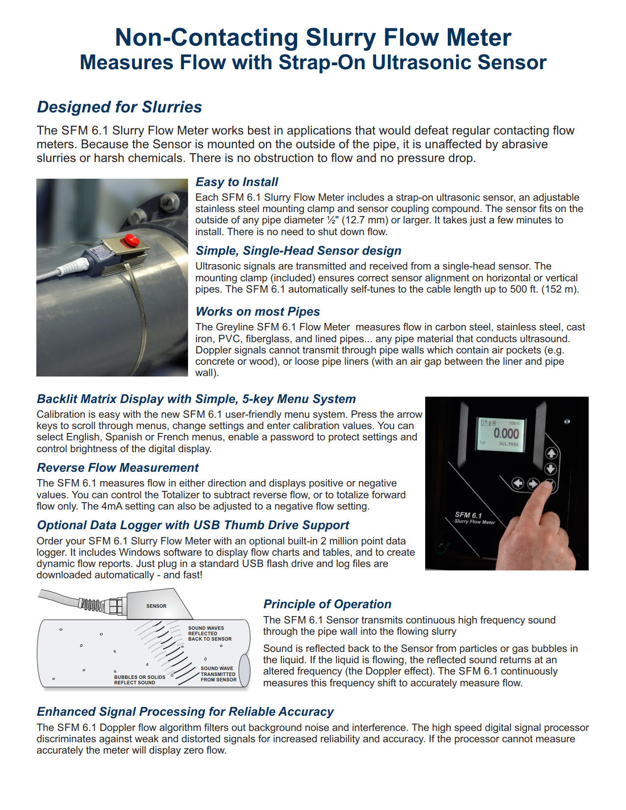
Easy to Install
Each SFM 6.1 Slurry Flow Meter includes a strap-on ultrasonic sensor, an adjustable stainless steel mounting clamp and sensor coupling compound. The sensor fits on the outside of any pipe diameter ?” (12.7 mm) or larger. It takes just a few minutes to install. There is no need to shut down flow.
Special Features
- Digital processing system tracks flow signals accurately and auto-zeroes with signal loss
- Noise suppression circuitry filters “dirty” power and electrical interference from most VFD’s
- Automatically converts between measurement units (e.g. gallons or liters)
- Calibration data and Totalizer values are stored automatically during power interruptions
- Output “simulation” function simplifies calibration of remote devices (e.g. chart recorders or controllers)
- Self-tunes to Sensor cable length
泥浆流量计规格
范围:本规范涵盖由Greyline Instruments Inc.,Largo,Florida/Long Sault,Ontario制造的非侵入式超声波多普勒泥浆流量计。仪器应提供速度或体积指示和传输全管中的流速。
A.性能规范
流量计应使用安装在外部的单头流量传感器进行操作,该传感器安装在任何传导声音的相邻管道材料上,包括:碳钢、不锈钢、球墨铸铁、铜、FRP、PVC、ABS或1/2“至180”(12.5 m m至4.5 m)ID的水泥内衬管道。
测量并显示从+0.25到+40 ft/sec和-0.25到-40 ft/sec(+0.075到+12.2 m/sec和-0.075到-12.2 m/sec)的流速,准确度为100微米或更大夹带颗粒或气体液体读数的±2%,最小浓度为75 ppm。
B.传感器(流量传感器)
流量传感器应为单头超声波不锈钢外壳。
它应安装在管道外部,不会中断流量。
传感器应能在-40°F至300°F(-40°C至150°C)的温度下连续工作,并能承受10 psi的意外淹没压力。
应包括制造商推荐的耦合化合物和不锈钢安装夹。
应包括20 ft(6 m)传感器电缆、屏蔽同轴对。
应能够将传感器电缆延伸至500 ft(152m),无需操作员调整。
应隔离变压器,并设计为满足本质安全要求。
应设计为射频干扰抑制,并包括附近雷击时自动高压泄放。
传感器应为I级2类A、B、C和D组位置的非易燃性。
C.传感器
/变送器
变送器指示器应安装在带窗户的NEMA4不锈钢内,并适用于墙壁安装。
流量计电子设备应设计为在-5°F至140°F(-20°C至60°C)的温度下工作。
电子电路可与其他具有相同型号的流量计互换。
发射机电路和校准频率标准应为晶体控制。
变送器应由100-240VAC 50/60HZ供电,要求小于5瓦特。
变送器应包括一个内置的5键校准系统,操作员可通过菜单校准系统的视觉提示选择参数。
不接受需要通过参数代码或外部校准器进行校准的系统。
4-20mA应与流量成比例并隔离,具有可编程零点和满刻度偏移。
最大电阻负载应为1000欧姆。
它应包括附近雷击时自动高压泄放。
应包括噪声抑制电路,以过滤电气干扰。
有一个白色背光矩阵液晶显示器,以用户选择的工程单位显示流量、校准单位、继电器状态、信号强度和16位积算器。
有2个额定电流为5安培SPDT的控制继电器。继电器应可编程用于流量比例脉冲输出,或作为具有单独开/关设定点的流量警报。
应显示并汇总正向和反向流量。
电子设备应为模块化,并可通过插入式电路板进行现场更换。
仪器应自动检测和加载软件菜单,以供现场安装选项使用。
D.按要求插入规范的附加功能:
传感器的本质安全等级应为I级,C、D组;II级,E、F、G组;
III级,带本质安全栅。
传感器电缆应为50 ft(15 m)长的屏蔽同轴对。
传感器电缆应为100 ft(30 m)长的屏蔽同轴对。
在导管中安装传感器电缆接线盒和总长度不超过500 ft(152m)的屏蔽同轴对电缆,以进行机械保护。
在温度低于-5°F(-20°C)的位置配备恒温控制的交流供电外壳加热器,以防冷凝。
电源输入为9-32Vdc。
内置200万点数据记录器,USB输出到闪存驱动器或大容量存储设备。
包括Windows软件。
E.制造商
仪器应为Greyline Instruments Inc.制造的SFM 6.1型泥浆流量计,并保证一年内不会出现材料和工艺缺陷。
如果您在申请中需要更多信息或建议,请联系Greyline。我们可以提供报价,并向贵公司所在地区的Greyline销售代表咨询。
SLURRY FLOW METER SPECIFICATIONS
SCOPE: This specification covers a non-intrusive, ultrasonic Doppler-type slurry flow meter as manufactured by Greyline Instruments Inc., Largo, Florida / Long Sault, Ontario. The instrument shall provide for velocity or volumetric indicating and transmitting of the flow rate in a full pipe.
A. PERFORMANCE SPECIFICATIONS
The flow meter shall operate with a single-head flow sensor mounted externally on any contiguous pipe material that conducts sound including: carbon steel, stainless steel, ductile iron, copper, FRP, PVC, ABS, or cement lined pipe from 1/2″ to 180″ (12.5 mm to 4.5 m) ID.
Measure and indicate flow rates from +0.25 to +40 ft/sec and -0.25 to -40 ft/sec (+0.075 to +12.2 m/sec and -0.075 to -12.2 m/sec) with accuracy of ±2% of reading on liquids with entrained particles or gases of 100 microns or larger and minimum concentrations of 75 ppm.
B. TRANSDUCER (FLOW SENSOR)
The flow sensor shall be single-head, ultrasonic in a stainless steel housing. It shall be installed on the outside of a pipe without interrupting flow. The sensor shall be capable of continuous operation at temperatures from -40°F to 300°F (-40°C to 150°C), and to withstand accidental submersion pressures to 10 psi. Manufacturer’s recommended coupling compound and stainless steel mounting clamp shall be included.
Shall include 20 ft (6m) Sensor cable, shielded coaxial pair.
Shall be capable of extending sensor cable up to 500 ft (152m) without requirement for operator adjustment.
Shall be transformer isolated and designed to meet intrinsic safe requirements. Shall be designed for maximum RFI rejection, and include automatic high voltage bleeds for nearby lightning strikes.
Sensor shall be rated Non-incendive for Class I, Division 2, Groups A, B, C & D locations.
C. TRANSMITTER
The transmitter indicator shall be housed in a NEMA4 stainless steel with window and suitable for wall mounting.
Flow meter electronics shall be designed to operate at temperatures from -5°F to 140°F (-20°C to 60°C). Electronic circuits are interchangeable with other flow meters having the same model number. The transmitter circuit and calibration frequency standard shall be crystal controlled. The transmitter shall be powered by 100-240VAC 50/60Hz requiring less than 5 Watts.
The transmitter shall include a built-in 5-Key calibration system with operator selection of parameters through visual prompts from a Menu calibration system. Systems requiring calibration by Parameter codes or external calibrators shall not be accepted.
The 4-20mA shall be flow proportional and isolated, with programmable zero and full scale offsets. Maximum resistive load shall be 1000 ohms. It shall include automatic high voltage bleeds for nearby lightning strikes.
Shall include noise suppression circuitry to filter electrical interference.
Have a white, backlit matrix LCD display indicating flow rate in user-selected engineering units, units of calibration, relay states, signal strength and 16-digit totalizer.
Have 2 control relays rated 5 ampere SPDT. Relays shall be programmable for flow proportional pulse output, or as flow rate alarms with separate ON/OFF set points.
Shall display and totalize forward and reverse flow.
Electronics shall be modular and field replaceable by means of plug-in circuit boards. The instrument shall detect and load software menus automatically for field-installed options.
D. ADDITIONAL FEATURES FOR INSERTION IN SPECIFICATION AS REQUIRED:
Sensor shall be rated intrinsically safe to Class I, Groups C,D; Class II, Groups E,F,G; Class III with Intrinsic Safety Barriers.
Sensor cable shall be 50 ft (15m) length shielded coaxial pair.
Sensor cable shall be 100 ft (30 m) length shielded coaxial pair.
Have a Sensor Cable Junction Box and up to 500 ft (152m) length total shielded coaxial pair cable installed in conduit for mechanical protection.
Have a thermostatically controlled AC-powered enclosure heater for condensation protection in locations with temperature below -5°F (-20°C).
Have power input of 9-32VDC.
Have a built-in 2 million point Data Logger with USB output to flash drive or mass storage device. Include Windows software.
E. MANUFACTURER
The instrument shall be a Model SFM 6.1 Slurry Flow Meter as manufactured by Greyline Instruments Inc., and warranted against defects in materials and workmanship for one year.
Please contact Greyline if you need more information or for advice in your application. We can provide quotations and refer you to the Greyline sales representative in your area.
流量计运作原理
仪器电子设备测量从发送声音到回声返回所需的时间。根据空气中的声速,可以高精度计算出液体表面与传感器的准确距离(0.25%范围)。
由于声速受空气温度的影响,灰线超声波液位传感器包括一个内置的温度传感器。水平/距离测量在传感器的整个工作温度范围内自动进行温度补偿。
传感器的位置应使其能清楚地“看到”液体表面,远离梯子、管道或其他障碍物。Greyline建议每10英尺深度距离侧壁1英尺(每3米深度300毫米)。来自搅拌器的假回波(在传感器下扫过)、湍流和波可以被仪器过滤和忽略。
Greyline模型的范围从简单的4-20mA液位指示发送器,到复杂的监控、控制和数据记录模型。返回greyline产品了解级别模型详细信息和规格。有关包括超声波在内的各种液位仪表技术的信息,请参阅废水液位测量技术。
测量管外脏污或充气液体的流量
多普勒效应由奥地利物理学家克里斯蒂安·多普勒于1842年提出。我们每天都能听到多普勒的例子:火车经过时的汽笛声改变音调,或者赛车驶过我们的位置时的排气噪音。
多普勒技术只适用于含有固体或气泡的液体来反射其信号。这些是“困难”的液体,可能会损坏常规流量计:泥浆、污泥、废水、磨料、粘性和腐蚀性化学品。由于传感器安装在管道外部,因此没有压降,也没有流动障碍物。
为了获得很好性能,多普勒传感器应安装在远离湍流产生装置(如弯管和三通)的地方,远离速度增加装置(如控制阀和泵)。典型精度为满刻度的±2%。多普勒仪器包括一个夹式超声波传感器、连接电缆和一个电子外壳,可以安装在附近方便的位置(500英尺/152米范围内)。传感器可以本质安全地额定安装在危险的额定位置。
需要非常精确的定时电路,但当传感器可以安装在流量均匀分布的管段上时,1%的精度非常典型。
由于超声波信号必须穿过管道到达接收传感器,因此流体中不得含有大量气泡或固体(小于2%)。否则高频声音会减弱,太弱,无法穿过管道。应用包括饮用水、冷却水、水/乙二醇溶液、液压油、燃油和化学品。
渡越时间传感器通常工作在1-2兆赫的频率。高频设计通常用于较小的管道,低频设计用于直径达数米的大型管道。
水槽和堰是专门设计的渠道形状,以表征水流。常见的类型有矩形堰、V型槽堰、Parshall水槽和Palmer Bowlus水槽。水槽或堰型的选择取决于应用:流速、渠道形状和水的固体含量。请联系Greyline Instruments以获取有关为您的应用选择合适水槽或堰的建议。
灰线明渠流量计可以通过菜单选择校准到水槽或堰。明渠流量计电子设备使用内部公式计算流量(流量=k h n,其中“k”和“n”为常数,“h”为仪器测量的压头)。通过直接输入“k”和“n”常数,可以对不常见或自定义水槽进行校准。Greyline还提供了一个PC软件程序“find k&n”,用于根据水槽或堰流图开发校准常数。
Greyline明渠流量计包括非接触式超声波传感器、连接电缆和电子外壳,可安装在附近方便的位置(500 ft/152 m内)。传感器可以本质安全地额定安装在危险的额定位置。仪器显示、汇总、传输和控制,有些型号包括数据记录/流量报告系统。
在没有水槽或堰的情况下测量明渠流量。面积速度流量计连续测量水位和流速,以计算明渠或管道中的流量。
超声波传感器安装在管道或通道的底部。为了测量水位,传感器发送超声波脉冲,这些脉冲通过水传播并从液体表面反射出来。仪器精确测量回声返回传感器所需的时间。根据水中声速,测量声级精度为±0.25%。
用连续注入水中的超声多普勒信号测量流速。这种高频声音(640kHz)从悬浮在液体中的颗粒或气泡反射回传感器。如果流体在运动,回声以与流速成比例的变化频率返回。利用该技术,仪器测量流速的精度为±2%。
greyline面积流速流量计工作在部分满管和溢流管、矩形、梯形和蛋形通道中。
可选-单独的液位和速度传感器
一个单独的向下看超声波传感器可用于高充气或湍流应用。它通过将超声波脉冲通过空气传输到液体表面来测量液位,精度为±0.25%。在水位传感器的基础上,采用水下多普勒速度传感器对水位进行测量。
HOW IT WORKS
The instrument electronics measure the time it takes from transmitted sound to return of the echo. With reference to the speed of sound in air, the exact distance of the liquid surface from the sensor can be calculated with high accuracy (±0.25% of maximum range).
Since the speed of sound is affected by air temperature, Greyline ultrasonic level sensors include a built-in temperature sensor. Level/distance measurements are automatically temperature compensated throughout the operating temperature range of the sensor.
The sensor should be positioned so that it has a clear “view” of the liquid surface and away from ladders, pipes or other obstructions. Greyline recommends 1 ft. from the sidewall for every 10 ft. depth (300 mm for every 3 m depth). False echoes from agitators (sweeping under the sensor), turbulence and waves can be filtered and disregarded by the instrument.
Greyline models range from simple 4-20mA level indicating transmitters, to sophisticated monitoring, controlling and data logging models. Return to Greyline Products for Level model details and specifications. For information on a wide range of level instrument technologies including ultrasonics, read Wastewater Level Measurement Techniques.
Doppler flow meters measure flow from outside a pipe with a clamp-on sensor. Greyline Doppler meters continuously transmit high frequency sound (640 kHz) that travels through the pipe wall and into the flowing liquid. Sound is reflected back to the sensor from solids or bubbles in the fluid. If the fluid is in motion, the echoes return at an altered frequency proportionate to flow velocity. Doppler flow meters continuously measure this frequency shift to calculate flow.
Measure Flow of dirty or aerated Liquids from Outside a Pipe
The Doppler effect was first documented in 1842 by Christian Doppler, an Austrian physicist. We hear everyday examples of Doppler: the sound of a train whistle changing pitch as it passes by, or the exhaust noise from a race car as it speeds past our location.
The Doppler technique only works on liquids which contain solids or gas bubbles to reflect its signal. These are “difficult” liquids that may damage regular flow meters: slurries, sludge, wastewater, abrasives, viscous and corrosive chemicals. Because the sensor mounts on the outside of the pipe, there is no pressure drop and no obstruction to flow.
For best performance Doppler sensors should be mounted away from turbulence creating devices like pipe elbows and tees, and away from velocity increasing devices like controlling valves and pumps. Typical accuracy is ±2% of full scale. Doppler instruments include a clamp-on ultrasonic sensor, connecting cable and an electronics enclosure which can be mounted at a convenient location nearby (within 500 ft / 152 m). Sensors can be rated intrinsically safe for mounting in hazardous-rated locations.
Very accurate timing circuits are required but 1% accuracy is quite typical when the transducers can be mounted on a pipe section with evenly distributed flow.
Because the ultrasonic signal must cross the pipe to a receiving transducer, the fluid must not contain a significant concentration of bubbles or solids (less than 2%). Otherwise the high frequency sound will be attenuated and too weak to traverse the pipe. Applications include potable water, cooling water, water/glycol solutions, hydraulic oil, fuel oils and chemicals.
Transit Time transducers typically operate in the 1-2 MHz frequencies. Higher frequency designs are normally used in smaller pipes and lower frequencies for large pipes up to several meters in diameter.
Flumes and weirs are specially designed channel shapes that characterize the flow of water. Common types are Rectangular Weirs, V-Notch Weirs, Parshall flumes and Palmer Bowlus flumes. The choice of flume or weir type depends on the application: flow rate, channel shape and solids content of the water. Contact Greyline Instruments for advice on selection of a suitable flume or weir for your application.
Greyline open channel flow meters can be calibrated to any flume or weir by menu selection. The open channel flow meter electronics use an internal formula to calculate flow rate (Flow = K Hn, where ‘K’ and ‘n’ are constants and ‘H’ is Head as measured by the instrument). Calibration to uncommon or custom flumes can be done by direct entry of ‘K’ and ‘n’ constants. Greyline also offers a PC software program “Find K&n” to develop calibration constants from a flume or weir flow chart.
Greyline open channel flow meters include a non-contacting ultrasonic sensor, connecting cable and an electronics enclosure which can be mounted at a convenient location nearby (within 500 ft / 152 m). Sensors can be rated intrinsically safe for mounting in hazardous-rated locations. The instruments display, totalize, transmit and control, and some models include data logging/flow reporting systems.
Measure open channel flow without a flume or weir An Area-Velocity Flow Meter continuously measures both Level and Velocity to calculate flow volume in an open channel or pipe.
The ultrasonic sensor is installed at the bottom of a pipe or channel. To measure water level the sensor transmits ultrasonic pulses that travel through the water and reflect off the liquid surface. The instrument precisely measures the time it takes for echoes to return to the sensor. Based on the speed of sound in water, the level is measured with accuracy of ±0.25%.
Flow velocity is measured with an ultrasonic Doppler signal continuously injected into the water. This high frequency sound (640 KHz) is reflected back to the sensor from particles or bubbles suspended in the liquid. If the fluid is in motion, the echoes return at an altered frequency proportionate to flow velocity. With this technique the instrument measures flow velocity with accuracy of ±2%.
Greyline Area-Velocity Flow Meters work in partially full and surcharged pipes, rectangular, trapezoid and egg-shaped channels.
Optional – Separate Level and Velocity Sensors
A separate down-looking ultrasonic sensor can be used for highly aerated or turbulent flow applications. It measures level by transmitting ultrasonic pulses through the air to the liquid surface with accuracy of ±0.25%. Along with the level sensor, a submerged Doppler velocity sensor is used to measure the water velocity.


