


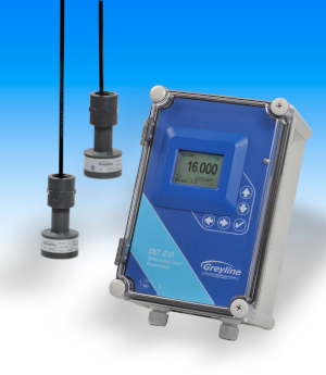
DLT 2.0差分电平变送器
- 测量水平,差异水平和明渠流量
- 两个非接触式超声波传感器
- 大型白色背光液晶显示器
- 三个隔离的4-20mA输出
- 内置5键校准
- 2个可编程控制继电器
- 可选的2百万点数据记录器
- 可选的本质安全传感器
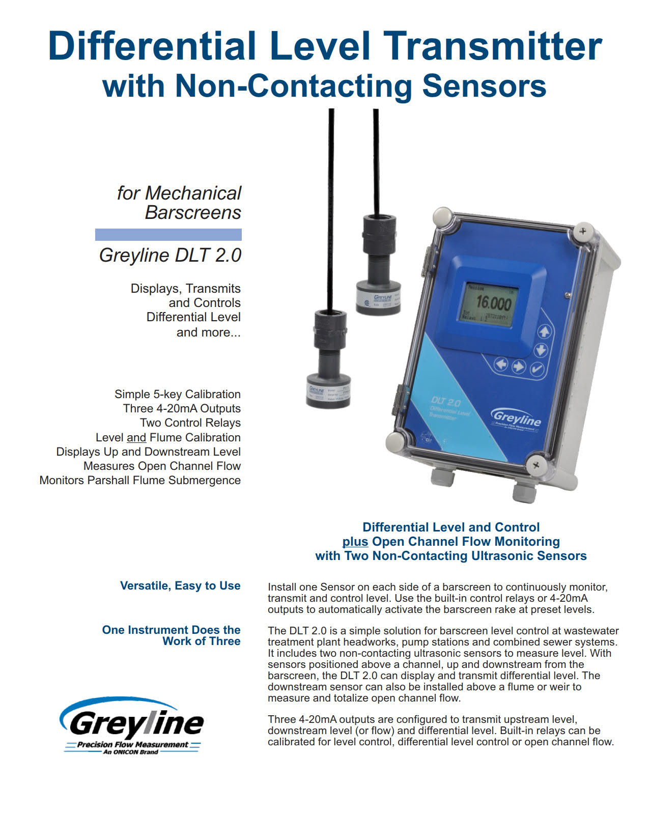
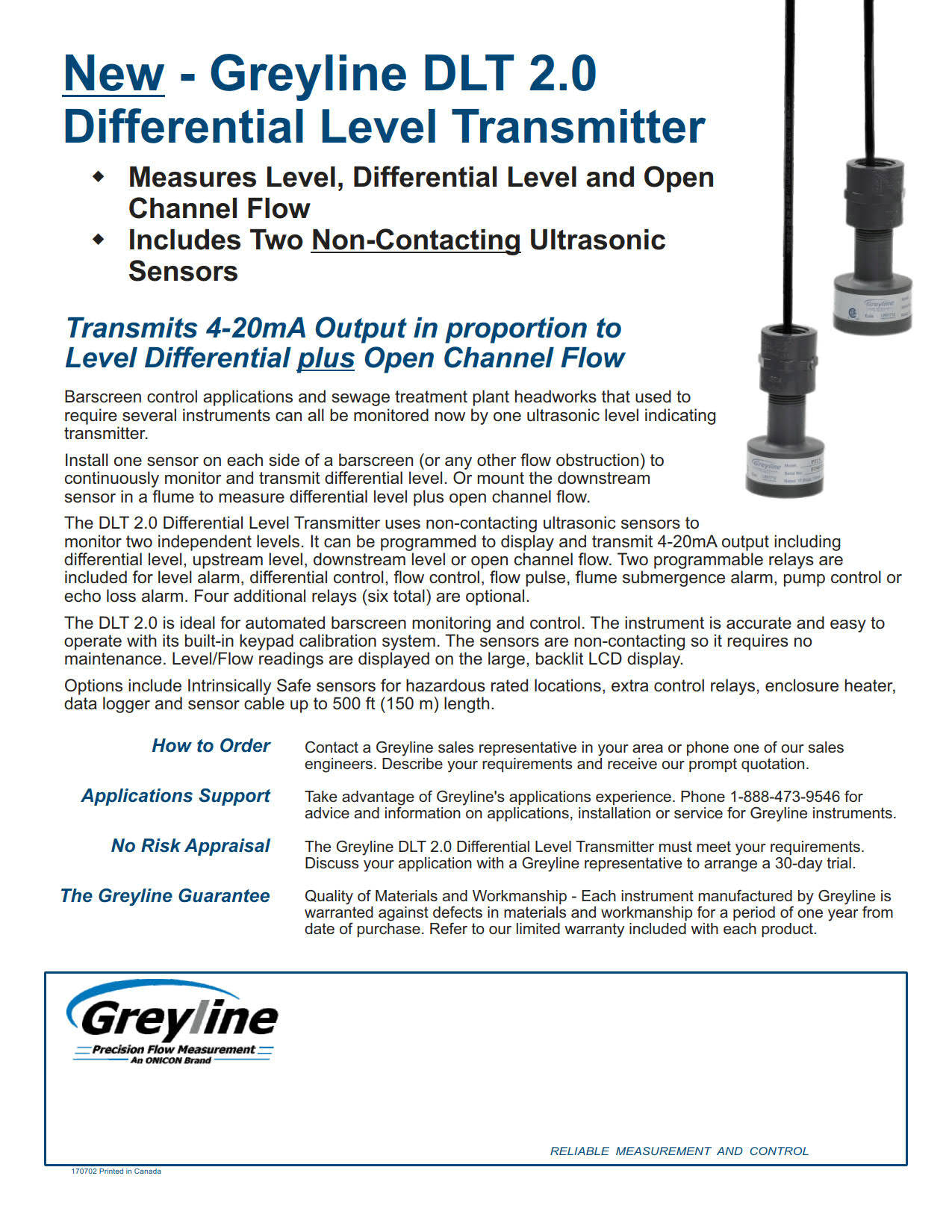
DLT 2.0 Differential Level Transmitter
- Measures Level, Differential Level and Open Channel Flow
- Two Non-Contacting Ultrasonic Sensors
- Large White Backlit LCD Display
- Three Isolated 4-20mA Outputs
- Built-in 5-Key Calibration
- 2 Programmable Control Relays
- Optional 2 Million Point Data Logger
- Optional Intrinsically Safe Sensors
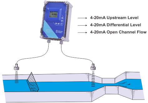
降低成本并简化处理厂头部的仪器设备。DLT 2.0可以测量差动水平和通过水槽的流量。在机械条屏幕的每一侧安装一个传感器,以持续监控,传输和控制水平。使用内置控制继电器或4-20mA输出自动激活预设水平的条屏耙。
DLT 2.0是废水处理厂,泵站和综合下水道系统中酒吧水平控制的简单解决方案。它包括两个非接触式超声波传感器来测量水平。传感器位于通道上方,屏幕上方和下游,DLT 2.0可以显示和传输差分电平。下游传感器也可以安装在水槽或堰上方,以测量和累计明渠流量。
三个4-20mA输出配置为传输上游级别,下游级别(或流量)和差异级别。内置继电器可以进行电平控制,差分电平控制或明渠流量校准。
其他DLT 2.0应用包括双罐库存,您可以使用一台仪器监控两个罐中的液位。DLT 2.0将在两个储罐中交替显示液位,并传输4-20mA输出。使用内置继电器激活警报或电平控制。这款多功能双传感器仪器还可配置为Parshall水槽的浸没式报警器。
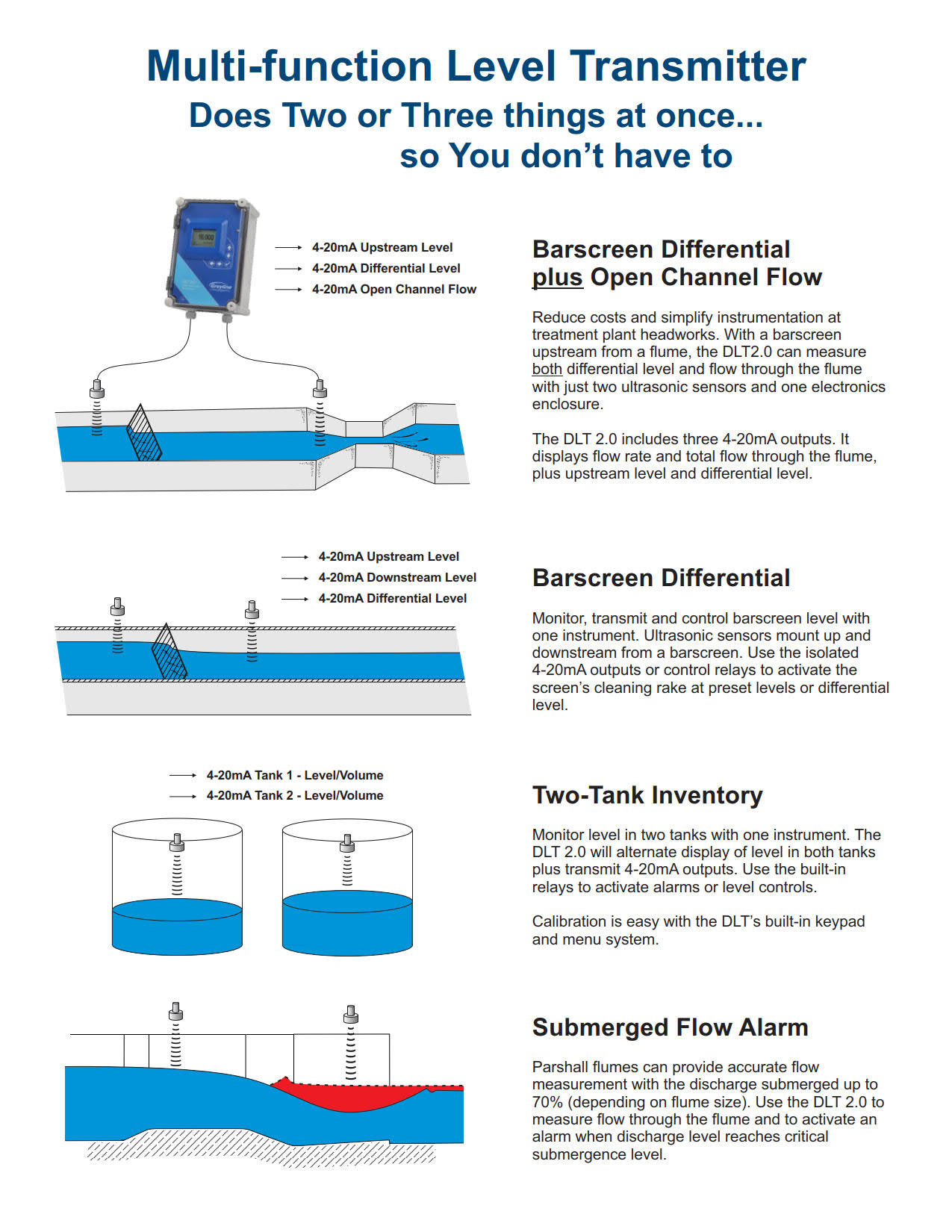
Reduce costs and simplify instrumentation at treatment plant headworks. The DLT 2.0 can measure both differential level plus flow through a flume. Install one Sensor on each side of a mechanical barscreen to continuously monitor, transmit and control level. Use the built-in control relays or 4-20mA outputs to automatically activate the barscreen rake at preset levels.
The DLT 2.0 is a simple solution for barscreen level control at wastewater treatment plants, pump stations and combined sewer systems. It includes two non-contacting ultrasonic sensors to measure level. With sensors positioned above a channel, up and downstream from the barscreen, the DLT 2.0 can display and transmit differential level. The downstream sensor can also be installed above a flume or weir to measure and totalize open channel flow.
Three 4-20mA outputs are configured to transmit upstream level, downstream level (or flow) and differential level. Built-in relays can be calibrated for level control, differential level control or open channel flow.
Other DLT 2.0 applications include two-tank inventory where you can monitor level in two tanks with one instrument. The DLT 2.0 will alternate display of level in both tanks plus transmit 4-20mA outputs. Use the built-in relays to activate alarms or level controls. This versatile dual-sensor instrument can also be configured as a submergence alarm for Parshall flumes.
差分液位变送器规格
范围:本规范涵盖由Greyline Instruments,Largo,Florida/Long Sault,Ontario制造的非接触式超声波差动液位传感器。
该仪器应提供通过水槽、堰或其他主要测量装置指示、传输和控制水位、筛差水位和明渠流量。
A.通用
差分液位传感器由两个非接触式超声波传感器、连接电缆和带指示、传输和控制电子设备的远程外壳组成。
测量精度应为量程的±0.25%或2 mm(0.08”),以较大者为准,并应自动进行温度补偿。
传感器电缆长度应符合安装要求,不得超过500 ft(152 m)。
系统应无活动部件,且不得接触被测材料。
B.传感元件
超声波传感器应由聚氯乙烯制成。
传感器的最小死区或空白区为8”(203.2 m m),最大范围为15 ft.(4.57 m),工作频率为92 kHz,超声波束角为8度。
传感器应能承受20 psi(1.4 bar)的意外淹没。
传感器工作温度应为-40°F至150°F(-40°C至65°C)。
传感器应包括整体式温度传感器。
不接受需要单独安装和布线的温度传感器。
C.传感器连接电缆
提供连续长度为25英尺(7.6米)的RG62AU同轴电缆,并在传感器头上进行防水封装连接。
每个传感器的延伸传感器电缆应为RG62AU同轴电缆,最大500’(152m)。
电缆应采用制造商推荐的NEMA4钢接线盒中的螺纹终端连接进行拼接。
水平和温度信号应在一根同轴电缆上进行。
不接受单独或多芯电缆。
传感器电缆应安装在接地金属导管中。
D.发射机
变送器
应包括一个内置的5键校准系统,操作员可通过菜单校准系统的视觉提示选择参数。
不接受需要通过参数代码或外部校准器进行校准的系统。
校准数据应通过断电永久存储,无需备用电池。
现场校准应允许选择和自动转换测量单位、测量范围和控制继电器。
变送器应在用户选择的液位、范围和/或明渠流量模式下进行现场校准。
操作模式应为用户可选择的差液位、差液位加明渠流量、两个水箱中的液位/体积或Parshall水槽中的淹没流量警报。
发射机应允许现场可编程阻尼,以便在湍流水平条件下平滑输出,并忽略来自波和伪回波的假信号。
变送器电子设备的工作温度应为-5°至140°F(-20°至60°C)。
变送器应具有三个独立的4-20mA输出,每个输出最大负载为1000 ohm。
输出应允许水平、差动水平和明渠流量的现场可编程偏移为4ma和20ma。
提供2个额定电流为5安培SPDT的控制继电器干触点。
继电器应可编程用于液位报警、差分液位控制、温度报警、泵控制、泵切换、流量积算器脉冲和/或回波损失报警。
提供一个白色背光矩阵LCD显示器,以用户选择的工程单位显示液位、差分液位、流量、积算器和继电器状态。
变送器应安装在壁装式防水NEMA4X(IP 66)外壳内,并配有铰链式透明盖。应包括安装硬件。
无需打开盖子,变送器LCD显示器应可见。
发送器电子设备应包括附近雷击时的自动高压泄放装置。
电子设备应为模块化,并可通过插入式电路板进行现场更换。
仪器应自动检测和加载软件菜单,以供现场安装选项使用。
变送器应由100-240VAC 50/60HZ供电,要求小于3瓦特。
E.根据需要插入的可选功能
有4个额外(共6个)控制继电器,额定5安培SPDT,可编程用于液位报警、差速液位控制、温度报警、泵控制、泵交替、流量积算器脉冲和/或回波损失报警。
传感器、连接电缆和接线盒的本质安全等级应为I、II、III级,I、II类,C、D、E、F、G组。
有一个恒温控制的外壳加热器,用于温度低于冰点时的变送器操作。
具有两个PZ34T非接触式超声波PVC传感器,测量范围高达32 ft(10 m),最小死区或空白16”(406 m m)。
使用制造商推荐的外壳防晒霜,以便在阳光直射下安装变送器。
使用制造商推荐的传感器防晒霜,以便在阳光直射下安装温度补偿传感器。
为外壳安装提供制造商推荐的面板安装法兰组件。
内置200万点数据记录器,USB输出到闪存驱动器或大容量存储设备。
变送器电源输入应为9-32Vdc,最大功耗不超过3瓦特。
F.制造商
DLT 2.0差分液位变送器应为Greyline Instruments Inc.制造的DLT 2.0型,并应保证一年内不会出现材料和工艺缺陷。
规格如有更改,恕不另行通知。如果您在申请中需要更多信息或建议,请联系Greyline。我们可以提供报价,并向贵公司所在地区的Greyline销售代表咨询。
DIFFERENTIAL LEVEL TRANSMITTER SPECIFICATIONS
SCOPE: This specification covers a non-contacting ultrasonic Differential Level Transmitter as manufactured by Greyline Instruments, Largo, Florida / Long Sault, Ontario. This instrument shall provide for indicating, transmitting and control of level, barscreen differential level and open channel flow through a flume, weir, or other primary measuring device.
A. GENERAL
Differential Level Transmitter to consist of two non-contacting ultrasonic sensors, connecting cable, and a remote enclosure with indicating, transmitting and controlling electronics.
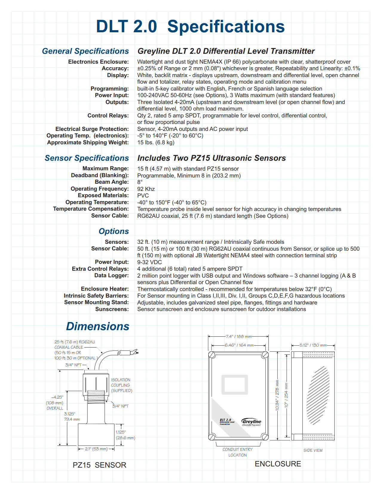
Measurement accuracy shall be ±0.25% of Range or 2 mm (0.08″), whichever is greater, and shall be automatically temperature compensated.
Sensor cable length shall be as required by installation, not to exceed 500 ft (152 m).
System shall have no moving parts and shall not contact the material being measured.
B. SENSING ELEMENT
Ultrasonic sensors shall be constructed of PVC.
Sensors shall have a minimum deadband or blanking of 8″ (203.2 mm) and a maximum range of 15 ft. (4.57 m), and have an operating frequency of 92 kHz with an ultrasonic beam angle of 8 Degrees.
Sensors shall withstand accidental submersion to 20 psi (1.4 bar).
Sensor operating temperature shall be from -40°F to 150°F (-40°C to 65°C).
Sensors shall include integral temperature sensor. Temperature sensors requiring separate mounting and wire runs shall not be accepted.
C. SENSOR CONNECTING CABLE
Provide RG62AU coaxial cable 25′ (7.6m) continuous length, with waterproof, potted bond to the Sensor head.
Extended sensor cable shall be RG62AU coaxial to a maximum of 500′ (152m) for each sensor. Cable shall be spliced with screw terminal connections in manufacturer’s recommended steel NEMA4 Junction Box.
Level and temperature signals shall be conducted on one single coaxial cable. Separate or multiple-conductor cables shall not be accepted.
Sensor cable shall be installed in grounded metal conduit.
D. TRANSMITTER
The transmitter shall include a built-in 5-Key calibration system with operator selection of parameters through visual prompts from a Menu calibration system. Systems requiring calibration by Parameter codes or external calibrators shall not be accepted..
Calibration data shall be permanently stored through power interruptions without requirement of a back-up battery.
Field calibration shall allow selection and automatic conversion of measurement units, measurement span and control relays.
The transmitter shall provide for field calibration in user-selected Level, Range and/or Open Channel Flow modes. Operation mode shall be user-selectable for differential level, differential level plus open channel flow, level/volume in two tanks or submerged flow alarm in Parshall flumes.
Transmitter shall permit field programmable damping to smooth output in turbulent level conditions and to disregard false signals from waves and spurious echoes.
Transmitter electronics operating temperature shall be from -5° to 140°F (-20° to 60°C).
Transmitter shall have three isolated 4-20mA outputs each with 1000 ohm maximum load. Outputs shall allow field programmable offsets of 4mA and 20mA for level, differential level and open channel flow.
Provide 2 control relay dry contacts rated 5 ampere SPDT. Relays shall be programmable for level alarm, differential level control, temperature alarm, pump control, pump alternation, flow totalizer pulse and/or echo loss alarm.
Provide a white, backlit matrix LCD display indicating level, differential level, flow rate, totalizer and relay states in user-selected engineering units.
Transmitter shall be housed in a wall-mount, watertight NEMA4X (IP 66) enclosure with hinged, clear cover. Mounting hardware shall be included.
Transmitter LCD display shall be visible without opening cover.
Transmitter electronics shall include automatic high voltage bleeds for nearby lightning strikes.
Electronics shall be modular and field replaceable by means of plug-in circuit boards. The instrument shall detect and load software menus automatically for field-installed options.
The transmitter shall be powered by 100-240VAC 50/60Hz requiring less than 3 Watts.
E. OPTIONAL FEATURES FOR INSERTION AS REQUIRED
Have 4 additional (6 total) control relays, rated 5 amp SPDT and programmable for level alarm, differential level control, temperature alarm, pump control, pump alternation, flow totalizer pulse and/or echo loss alarm.
Sensor, connecting cable and junction boxes shall be rated intrinsically safe to Class I,II,III, Div. I,II, Groups C,D,E,F,G.
Have a thermostat controlled enclosure heater for Transmitter operation at temperatures below freezing.
Have two PZ34T non-contacting ultrasonic PVC sensors rated for measurement range up to 32 ft (10 m) with minimum deadband or blanking of 16″ (406 mm).
Have manufacturer’s recommended enclosure sunscreen to permit Transmitter mounting in direct sunlight.
Have manufacturer’s recommended Sensor sunscreen to permit temperature-compensated Sensor mounting in direct sunlight.
Have manufacturer’s recommended Panel Mount Flange assembly for enclosure installation.
Have a built-in 2 million point Data Logger with USB output to flash drive or mass storage device.
Transmitter power input shall be 9-32VDC with maximum power consumption of 3 watts or less.
F. MANUFACTURER
DLT 2.0 Differential Level Transmitter shall be Model DLT 2.0 as manufactured by Greyline Instruments Inc. and shall be warranted against defects in materials and workmanship for one year.
Specifications are subject to change without notice. Please contact Greyline if you need more information or for advice in your application. We can provide quotations and refer you to the Greyline sales representative in your area.
流量计运作原理
仪器电子设备测量从发送声音到回声返回所需的时间。根据空气中的声速,可以高精度计算出液体表面与传感器的准确距离(0.25%范围)。
由于声速受空气温度的影响,灰线超声波液位传感器包括一个内置的温度传感器。水平/距离测量在传感器的整个工作温度范围内自动进行温度补偿。
传感器的位置应使其能清楚地“看到”液体表面,远离梯子、管道或其他障碍物。Greyline建议每10英尺深度距离侧壁1英尺(每3米深度300毫米)。来自搅拌器的假回波(在传感器下扫过)、湍流和波可以被仪器过滤和忽略。
Greyline模型的范围从简单的4-20mA液位指示发送器,到复杂的监控、控制和数据记录模型。返回greyline产品了解级别模型详细信息和规格。有关包括超声波在内的各种液位仪表技术的信息,请参阅废水液位测量技术。
测量管外脏污或充气液体的流量
多普勒效应由奥地利物理学家克里斯蒂安·多普勒于1842年提出。我们每天都能听到多普勒的例子:火车经过时的汽笛声改变音调,或者赛车驶过我们的位置时的排气噪音。
多普勒技术只适用于含有固体或气泡的液体来反射其信号。这些是“困难”的液体,可能会损坏常规流量计:泥浆、污泥、废水、磨料、粘性和腐蚀性化学品。由于传感器安装在管道外部,因此没有压降,也没有流动障碍物。
为了获得很好性能,多普勒传感器应安装在远离湍流产生装置(如弯管和三通)的地方,远离速度增加装置(如控制阀和泵)。典型精度为满刻度的±2%。多普勒仪器包括一个夹式超声波传感器、连接电缆和一个电子外壳,可以安装在附近方便的位置(500英尺/152米范围内)。传感器可以本质安全地额定安装在危险的额定位置。
需要非常精确的定时电路,但当传感器可以安装在流量均匀分布的管段上时,1%的精度非常典型。
由于超声波信号必须穿过管道到达接收传感器,因此流体中不得含有大量气泡或固体(小于2%)。否则高频声音会减弱,太弱,无法穿过管道。应用包括饮用水、冷却水、水/乙二醇溶液、液压油、燃油和化学品。
渡越时间传感器通常工作在1-2兆赫的频率。高频设计通常用于较小的管道,低频设计用于直径达数米的大型管道。
水槽和堰是专门设计的渠道形状,以表征水流。常见的类型有矩形堰、V型槽堰、Parshall水槽和Palmer Bowlus水槽。水槽或堰型的选择取决于应用:流速、渠道形状和水的固体含量。请联系Greyline Instruments以获取有关为您的应用选择合适水槽或堰的建议。
灰线明渠流量计可以通过菜单选择校准到水槽或堰。明渠流量计电子设备使用内部公式计算流量(流量=k h n,其中“k”和“n”为常数,“h”为仪器测量的压头)。通过直接输入“k”和“n”常数,可以对不常见或自定义水槽进行校准。Greyline还提供了一个PC软件程序“find k&n”,用于根据水槽或堰流图开发校准常数。
Greyline明渠流量计包括非接触式超声波传感器、连接电缆和电子外壳,可安装在附近方便的位置(500 ft/152 m内)。传感器可以本质安全地额定安装在危险的额定位置。仪器显示、汇总、传输和控制,有些型号包括数据记录/流量报告系统。
在没有水槽或堰的情况下测量明渠流量。面积速度流量计连续测量水位和流速,以计算明渠或管道中的流量。
超声波传感器安装在管道或通道的底部。为了测量水位,传感器发送超声波脉冲,这些脉冲通过水传播并从液体表面反射出来。仪器精确测量回声返回传感器所需的时间。根据水中声速,测量声级精度为±0.25%。
用连续注入水中的超声多普勒信号测量流速。这种高频声音(640kHz)从悬浮在液体中的颗粒或气泡反射回传感器。如果流体在运动,回声以与流速成比例的变化频率返回。利用该技术,仪器测量流速的精度为±2%。
greyline面积流速流量计工作在部分满管和溢流管、矩形、梯形和蛋形通道中。
可选-单独的液位和速度传感器
一个单独的向下看超声波传感器可用于高充气或湍流应用。它通过将超声波脉冲通过空气传输到液体表面来测量液位,精度为±0.25%。在水位传感器的基础上,采用水下多普勒速度传感器对水位进行测量。
HOW IT WORKS
The instrument electronics measure the time it takes from transmitted sound to return of the echo. With reference to the speed of sound in air, the exact distance of the liquid surface from the sensor can be calculated with high accuracy (±0.25% of maximum range).
Since the speed of sound is affected by air temperature, Greyline ultrasonic level sensors include a built-in temperature sensor. Level/distance measurements are automatically temperature compensated throughout the operating temperature range of the sensor.
The sensor should be positioned so that it has a clear “view” of the liquid surface and away from ladders, pipes or other obstructions. Greyline recommends 1 ft. from the sidewall for every 10 ft. depth (300 mm for every 3 m depth). False echoes from agitators (sweeping under the sensor), turbulence and waves can be filtered and disregarded by the instrument.
Greyline models range from simple 4-20mA level indicating transmitters, to sophisticated monitoring, controlling and data logging models. Return to Greyline Products for Level model details and specifications. For information on a wide range of level instrument technologies including ultrasonics, read Wastewater Level Measurement Techniques.
Doppler flow meters measure flow from outside a pipe with a clamp-on sensor. Greyline Doppler meters continuously transmit high frequency sound (640 kHz) that travels through the pipe wall and into the flowing liquid. Sound is reflected back to the sensor from solids or bubbles in the fluid. If the fluid is in motion, the echoes return at an altered frequency proportionate to flow velocity. Doppler flow meters continuously measure this frequency shift to calculate flow.
Measure Flow of dirty or aerated Liquids from Outside a Pipe
The Doppler effect was first documented in 1842 by Christian Doppler, an Austrian physicist. We hear everyday examples of Doppler: the sound of a train whistle changing pitch as it passes by, or the exhaust noise from a race car as it speeds past our location.
The Doppler technique only works on liquids which contain solids or gas bubbles to reflect its signal. These are “difficult” liquids that may damage regular flow meters: slurries, sludge, wastewater, abrasives, viscous and corrosive chemicals. Because the sensor mounts on the outside of the pipe, there is no pressure drop and no obstruction to flow.
For best performance Doppler sensors should be mounted away from turbulence creating devices like pipe elbows and tees, and away from velocity increasing devices like controlling valves and pumps. Typical accuracy is ±2% of full scale. Doppler instruments include a clamp-on ultrasonic sensor, connecting cable and an electronics enclosure which can be mounted at a convenient location nearby (within 500 ft / 152 m). Sensors can be rated intrinsically safe for mounting in hazardous-rated locations.
Very accurate timing circuits are required but 1% accuracy is quite typical when the transducers can be mounted on a pipe section with evenly distributed flow.
Because the ultrasonic signal must cross the pipe to a receiving transducer, the fluid must not contain a significant concentration of bubbles or solids (less than 2%). Otherwise the high frequency sound will be attenuated and too weak to traverse the pipe. Applications include potable water, cooling water, water/glycol solutions, hydraulic oil, fuel oils and chemicals.
Transit Time transducers typically operate in the 1-2 MHz frequencies. Higher frequency designs are normally used in smaller pipes and lower frequencies for large pipes up to several meters in diameter.
Flumes and weirs are specially designed channel shapes that characterize the flow of water. Common types are Rectangular Weirs, V-Notch Weirs, Parshall flumes and Palmer Bowlus flumes. The choice of flume or weir type depends on the application: flow rate, channel shape and solids content of the water. Contact Greyline Instruments for advice on selection of a suitable flume or weir for your application.
Greyline open channel flow meters can be calibrated to any flume or weir by menu selection. The open channel flow meter electronics use an internal formula to calculate flow rate (Flow = K Hn, where ‘K’ and ‘n’ are constants and ‘H’ is Head as measured by the instrument). Calibration to uncommon or custom flumes can be done by direct entry of ‘K’ and ‘n’ constants. Greyline also offers a PC software program “Find K&n” to develop calibration constants from a flume or weir flow chart.
Greyline open channel flow meters include a non-contacting ultrasonic sensor, connecting cable and an electronics enclosure which can be mounted at a convenient location nearby (within 500 ft / 152 m). Sensors can be rated intrinsically safe for mounting in hazardous-rated locations. The instruments display, totalize, transmit and control, and some models include data logging/flow reporting systems.
Measure open channel flow without a flume or weir An Area-Velocity Flow Meter continuously measures both Level and Velocity to calculate flow volume in an open channel or pipe.
The ultrasonic sensor is installed at the bottom of a pipe or channel. To measure water level the sensor transmits ultrasonic pulses that travel through the water and reflect off the liquid surface. The instrument precisely measures the time it takes for echoes to return to the sensor. Based on the speed of sound in water, the level is measured with accuracy of ±0.25%.
Flow velocity is measured with an ultrasonic Doppler signal continuously injected into the water. This high frequency sound (640 KHz) is reflected back to the sensor from particles or bubbles suspended in the liquid. If the fluid is in motion, the echoes return at an altered frequency proportionate to flow velocity. With this technique the instrument measures flow velocity with accuracy of ±2%.
Greyline Area-Velocity Flow Meters work in partially full and surcharged pipes, rectangular, trapezoid and egg-shaped channels.
Optional – Separate Level and Velocity Sensors
A separate down-looking ultrasonic sensor can be used for highly aerated or turbulent flow applications. It measures level by transmitting ultrasonic pulses through the air to the liquid surface with accuracy of ±0.25%. Along with the level sensor, a submerged Doppler velocity sensor is used to measure the water velocity.


